Original Posted By: Michael Perez
Okay, so if I guy an simple antenna and hook it up to the handheld, does theground plane have to be directly under the antenna?For example, could the antenna be back in the fin and the ground plane justbehind the pilots seat?And, what goes from the antenna to the ground plane, a ground wire?Stupid questions I know, but appreciate the help.Douwe________________________________________________________________________________Date: Thu, 22 Mar 2012 05:16:29 -0700 (PDT)
Pietenpol-List: question for the radio geeks
Re: Pietenpol-List: Inst. Panel design
Original Posted By: John Franklin
Re: Pietenpol-List: question for the radio geeks
Original Posted By: "TOM STINEMETZE"
Pietenpol-List: Re: question for the radio geeks
Original Posted By: "tools"
Subject: Pietenpol-List: Archer antennasI'm thinking of putting one of the Archer Model 6 (see ACS here _http://www.aircraftspruce.com/catalog/avpages/ ... nas_6.php_ (http://www.aircraftspruce.com/catalog/a ... nnas_6.php) ) in the rear fuselage of the Piet with a cable and BNC connector out to hook to a handheld.I figure this ought to have better transmit/receive properties than the rubber duckie on the handheld. Anybody got any experience with these? On another topic, after issues with the bungee style shocks before last year's Brodhead, I built a set of die spring shocks over the winter. Got them installed yesterday, taxi tested them and hopped around the pattern and did a wheel landing with them. They're a little stiffer than the bungee shocks but I Iike the fact that because the springs are in compression, the travel is limited by more than just a 1/8" safety cable. Still should be plentyof travel to damp out most of my landings...hehehe. They're off now and back home for painting. Matt PaxtonNX629ML________________________________________________________________________________Subject: Pietenpol-List: Re: question for the radio geeks
Subject: Pietenpol-List: Archer antennasI'm thinking of putting one of the Archer Model 6 (see ACS here _http://www.aircraftspruce.com/catalog/avpages/ ... nas_6.php_ (http://www.aircraftspruce.com/catalog/a ... nnas_6.php) ) in the rear fuselage of the Piet with a cable and BNC connector out to hook to a handheld.I figure this ought to have better transmit/receive properties than the rubber duckie on the handheld. Anybody got any experience with these? On another topic, after issues with the bungee style shocks before last year's Brodhead, I built a set of die spring shocks over the winter. Got them installed yesterday, taxi tested them and hopped around the pattern and did a wheel landing with them. They're a little stiffer than the bungee shocks but I Iike the fact that because the springs are in compression, the travel is limited by more than just a 1/8" safety cable. Still should be plentyof travel to damp out most of my landings...hehehe. They're off now and back home for painting. Matt PaxtonNX629ML________________________________________________________________________________Subject: Pietenpol-List: Re: question for the radio geeks
Re: Pietenpol-List: Re: question for the radio geeks
Original Posted By: Amsafetyc
Here's the deal on these antennas.What we're using is a vertical antenna. They need a "ground plane" to form properradiation patterns. Without them, the energy from the radio doesn't all goout the antenna, it bounces around in the antenna and feedline until it's allused up as heat or gets radiated all out of sync. Not a big deal, but lessensthe effectiveness of the antenna.The ground plane doesn't have to be a aluminum disc. It can be a pattern of wiresall spread out like wagon wheel spokes. The point is, you can use reallyfine wire and save weight if that's an issue where you are putting it. The samewith the antenna itself. At the power levels we're using, you don't need thatheavy stainless wire they use. The important property of it is the length,it's only that heavy to withstand wind forces when placed outside the airplane.The ground plane does need to be at the feedpoint of the antenna, and perpendicularto it. It's an unbalanced antenna, and we use unbalanced feedline to feedit, coax. The shielding conductor goes to the ground plane.The wavelength of the freqs we use is around 6 feet I suppose and that's importantbecause it relates to the optimum length of the antenna. It needs to be about1/2 wavelength for proper impedence. If it's not, then you need to "trick"the system into thinking it's that long, which you can do with coils, capacitors,coiling up the radiating element, etc. These all make the system workcorrectly, but again, lessen the effectiveness of the antenna. That's how thestubby antennas work, they're all coiled up. The point it, you can make a REALLY effective antenna by using a longer radiatingelement, and lighter because you can use a simple piece of wire, etc. Evenbetter, I seem to recall that if the radiating element of a vertical antennais 5/8 wavelength, it actually INCREASES your effective radiating power, it'scalled a gain antenna. I'll dig into my old ham radio books and see if I can't devise a more simple andmore better antenna that we could build into our piets and do better. We'relucky because our planes are wood. Also, it should be a lot cheaper.The best antenna I ever had for my 2 meter (144 mhz, same genre as our 120 to 130mhz stuff) handheld radio was home made from a piece of that old brown flatline antenna wire we used to run to our tv antennas taped to a piece of broomhandle I would just lay on the dashboard of my old van. It was called a "j pole"antenna. Cost nothing, worked really well on the metal dash of a big oldwork van. We could zip tie it along a fuse stringer and be done. Wouldn't weighor cost a thing, no ground plane, takes about 20 mins to make. I'll justhave to adjust some dimensions for the slightly different frequency. You feedit with cheap old 75 ohm coax that is hanging around behind your tv set. Theantenna was about 4 feet long or so. de n0kkjRead this topic online here:http://forums.matronics.com/viewtopic.p ... ___Subject: Re: Pietenpol-List: Re: question for the radio geeks
Here's the deal on these antennas.What we're using is a vertical antenna. They need a "ground plane" to form properradiation patterns. Without them, the energy from the radio doesn't all goout the antenna, it bounces around in the antenna and feedline until it's allused up as heat or gets radiated all out of sync. Not a big deal, but lessensthe effectiveness of the antenna.The ground plane doesn't have to be a aluminum disc. It can be a pattern of wiresall spread out like wagon wheel spokes. The point is, you can use reallyfine wire and save weight if that's an issue where you are putting it. The samewith the antenna itself. At the power levels we're using, you don't need thatheavy stainless wire they use. The important property of it is the length,it's only that heavy to withstand wind forces when placed outside the airplane.The ground plane does need to be at the feedpoint of the antenna, and perpendicularto it. It's an unbalanced antenna, and we use unbalanced feedline to feedit, coax. The shielding conductor goes to the ground plane.The wavelength of the freqs we use is around 6 feet I suppose and that's importantbecause it relates to the optimum length of the antenna. It needs to be about1/2 wavelength for proper impedence. If it's not, then you need to "trick"the system into thinking it's that long, which you can do with coils, capacitors,coiling up the radiating element, etc. These all make the system workcorrectly, but again, lessen the effectiveness of the antenna. That's how thestubby antennas work, they're all coiled up. The point it, you can make a REALLY effective antenna by using a longer radiatingelement, and lighter because you can use a simple piece of wire, etc. Evenbetter, I seem to recall that if the radiating element of a vertical antennais 5/8 wavelength, it actually INCREASES your effective radiating power, it'scalled a gain antenna. I'll dig into my old ham radio books and see if I can't devise a more simple andmore better antenna that we could build into our piets and do better. We'relucky because our planes are wood. Also, it should be a lot cheaper.The best antenna I ever had for my 2 meter (144 mhz, same genre as our 120 to 130mhz stuff) handheld radio was home made from a piece of that old brown flatline antenna wire we used to run to our tv antennas taped to a piece of broomhandle I would just lay on the dashboard of my old van. It was called a "j pole"antenna. Cost nothing, worked really well on the metal dash of a big oldwork van. We could zip tie it along a fuse stringer and be done. Wouldn't weighor cost a thing, no ground plane, takes about 20 mins to make. I'll justhave to adjust some dimensions for the slightly different frequency. You feedit with cheap old 75 ohm coax that is hanging around behind your tv set. Theantenna was about 4 feet long or so. de n0kkjRead this topic online here:http://forums.matronics.com/viewtopic.p ... ___Subject: Re: Pietenpol-List: Re: question for the radio geeks
Pietenpol-List: Re: question for the radio geeks
Original Posted By: "tools"
Looks like a great seminar and Brodhead work shop session and everybody leaveswith a useable antenna tuned and ready to install. Should we all plan on bringingour hand held radios?JohnSent from my iPhoneOn Mar 22, 2012, at 10:41 AM, "tools" wrote:> > Here's the deal on these antennas.> > What we're using is a vertical antenna. They need a "ground plane" to form properradiation patterns. Without them, the energy from the radio doesn't allgo out the antenna, it bounces around in the antenna and feedline until it'sall used up as heat or gets radiated all out of sync. Not a big deal, but lessensthe effectiveness of the antenna.> > The ground plane doesn't have to be a aluminum disc. It can be a pattern ofwires all spread out like wagon wheel spokes. The point is, you can use reallyfine wire and save weight if that's an issue where you are putting it. Thesame with the antenna itself. At the power levels we're using, you don't needthat heavy stainless wire they use. The important property of it is the length,it's only that heavy to withstand wind forces when placed outside the airplane.> > The ground plane does need to be at the feedpoint of the antenna, and perpendicularto it. It's an unbalanced antenna, and we use unbalanced feedline to feedit, coax. The shielding conductor goes to the ground plane.> > The wavelength of the freqs we use is around 6 feet I suppose and that's importantbecause it relates to the optimum length of the antenna. It needs to beabout 1/2 wavelength for proper impedence. If it's not, then you need to "trick"the system into thinking it's that long, which you can do with coils, capacitors,coiling up the radiating element, etc. These all make the system workcorrectly, but again, lessen the effectiveness of the antenna. That's how thestubby antennas work, they're all coiled up. > > The point it, you can make a REALLY effective antenna by using a longer radiatingelement, and lighter because you can use a simple piece of wire, etc. Evenbetter, I seem to recall that if the radiating element of a vertical antennais 5/8 wavelength, it actually INCREASES your effective radiating power, it'scalled a gain antenna. > > I'll dig into my old ham radio books and see if I can't devise a more simpleand more better antenna that we could build into our piets and do better. We'relucky because our planes are wood. Also, it should be a lot cheaper.> > The best antenna I ever had for my 2 meter (144 mhz, same genre as our 120 to130 mhz stuff) handheld radio was home made from a piece of that old brown flatline antenna wire we used to run to our tv antennas taped to a piece of broomhandle I would just lay on the dashboard of my old van. It was called a "jpole" antenna. Cost nothing, worked really well on the metal dash of a big oldwork van. We could zip tie it along a fuse stringer and be done. Wouldn'tweigh or cost a thing, no ground plane, takes about 20 mins to make. I'll justhave to adjust some dimensions for the slightly different frequency. You feedit with cheap old 75 ohm coax that is hanging around behind your tv set. The antenna was about 4 feet long or so. > > de n0kkj> > > > > Read this topic online here:> > http://forums.matronics.com/viewtopic.p ... 138#369138> > > > > > > > > > ________________________________________________________________________________Subject: Pietenpol-List: Re: question for the radio geeks
Looks like a great seminar and Brodhead work shop session and everybody leaveswith a useable antenna tuned and ready to install. Should we all plan on bringingour hand held radios?JohnSent from my iPhoneOn Mar 22, 2012, at 10:41 AM, "tools" wrote:> > Here's the deal on these antennas.> > What we're using is a vertical antenna. They need a "ground plane" to form properradiation patterns. Without them, the energy from the radio doesn't allgo out the antenna, it bounces around in the antenna and feedline until it'sall used up as heat or gets radiated all out of sync. Not a big deal, but lessensthe effectiveness of the antenna.> > The ground plane doesn't have to be a aluminum disc. It can be a pattern ofwires all spread out like wagon wheel spokes. The point is, you can use reallyfine wire and save weight if that's an issue where you are putting it. Thesame with the antenna itself. At the power levels we're using, you don't needthat heavy stainless wire they use. The important property of it is the length,it's only that heavy to withstand wind forces when placed outside the airplane.> > The ground plane does need to be at the feedpoint of the antenna, and perpendicularto it. It's an unbalanced antenna, and we use unbalanced feedline to feedit, coax. The shielding conductor goes to the ground plane.> > The wavelength of the freqs we use is around 6 feet I suppose and that's importantbecause it relates to the optimum length of the antenna. It needs to beabout 1/2 wavelength for proper impedence. If it's not, then you need to "trick"the system into thinking it's that long, which you can do with coils, capacitors,coiling up the radiating element, etc. These all make the system workcorrectly, but again, lessen the effectiveness of the antenna. That's how thestubby antennas work, they're all coiled up. > > The point it, you can make a REALLY effective antenna by using a longer radiatingelement, and lighter because you can use a simple piece of wire, etc. Evenbetter, I seem to recall that if the radiating element of a vertical antennais 5/8 wavelength, it actually INCREASES your effective radiating power, it'scalled a gain antenna. > > I'll dig into my old ham radio books and see if I can't devise a more simpleand more better antenna that we could build into our piets and do better. We'relucky because our planes are wood. Also, it should be a lot cheaper.> > The best antenna I ever had for my 2 meter (144 mhz, same genre as our 120 to130 mhz stuff) handheld radio was home made from a piece of that old brown flatline antenna wire we used to run to our tv antennas taped to a piece of broomhandle I would just lay on the dashboard of my old van. It was called a "jpole" antenna. Cost nothing, worked really well on the metal dash of a big oldwork van. We could zip tie it along a fuse stringer and be done. Wouldn'tweigh or cost a thing, no ground plane, takes about 20 mins to make. I'll justhave to adjust some dimensions for the slightly different frequency. You feedit with cheap old 75 ohm coax that is hanging around behind your tv set. The antenna was about 4 feet long or so. > > de n0kkj> > > > > Read this topic online here:> > http://forums.matronics.com/viewtopic.p ... 138#369138> > > > > > > > > > ________________________________________________________________________________Subject: Pietenpol-List: Re: question for the radio geeks
Pietenpol-List: Re: question for the radio geeks
Original Posted By: "K5YAC"
Ya, great idea. Everyone start checking your attic for that flat lead antennawire! I've got some laying around and I'll bring all I've got. It's 300ohm antenna feed line. There's a bigger (read wider spaced) stuff that's450 that will also work. You can also use solid copper wire as long as it'ssupported in a way that keeps all the parts of the antenna in the right placerelative to each other.I should have swr measuring equipment so we can tune them all to everyone's radioand plane.As it turns out, the hard part with antennas is getting them UP in the air... well...a problem for earthbound mortals!I used to play this stuff the most before the internet. Just did a quick googleon 2 meter jpole antennas and got a zillion hits. Guess I don't have to digout the old books.ToolsRead this topic online here:http://forums.matronics.com/viewtopic.p ... ___Subject: Pietenpol-List: Re: question for the radio geeks
Ya, great idea. Everyone start checking your attic for that flat lead antennawire! I've got some laying around and I'll bring all I've got. It's 300ohm antenna feed line. There's a bigger (read wider spaced) stuff that's450 that will also work. You can also use solid copper wire as long as it'ssupported in a way that keeps all the parts of the antenna in the right placerelative to each other.I should have swr measuring equipment so we can tune them all to everyone's radioand plane.As it turns out, the hard part with antennas is getting them UP in the air... well...a problem for earthbound mortals!I used to play this stuff the most before the internet. Just did a quick googleon 2 meter jpole antennas and got a zillion hits. Guess I don't have to digout the old books.ToolsRead this topic online here:http://forums.matronics.com/viewtopic.p ... ___Subject: Pietenpol-List: Re: question for the radio geeks
Pietenpol-List: Re: question for the radio geeks
Original Posted By: "tkreiner"
I concur with Jim... the ground plane is an active element in the antenna installation.Think of it as a "reflector" for the transmitted signals... it shouldbe mounted at the base of the driven element (antenna). For radio people, the term "antenna" includes all of the hardware at the end ofthe feed line as they work in unison to effectively transmit the RF energy inthe desired pattern. For a ground mounted antenna system, an efficient groundplane "reflects" radio signals upwards, away from the ground, which improvesgain by "reflecting" or "directing" RF energy into the air where it is most effective.For an airplane installation, most of your communications are air-to-ground,which I assume is why the Fly Baby installation is inverted. I haven'tread the article (looked at the pics), but I would think that the buildersintent was to reflect the RF outward and downward rather than upward into thestratosphere where no one is listening to him. This would theoretically improvegain, or in other words... range. Since this ground plane or "element" is not physically connected to the earth ground,it is more correct to refer to it as a counterpoise, which is in effectan electrical ground, or simulated ground plane.Below is a cross-sectional view of a typical omni-directional radiation pattern,the type of pattern you might expect with a vertical, whip, rubber ducky orany other type of single element vertically oriented antenna. Notice that thepattern is transmitted upwards away from the ground... the squiggly lines representa ground plane. So, imagine if you were to take that image and turn itsideways or upside down... yes, the radiation pattern would remain the same,but you would direct it differently. Antenna theory and constructing arrays can become a fairly complicated discussion,but the basic formulas and theory behind simple omni-directional antennasis fairly straightforward. Back to the ground plane (or counterpoise)... giventhat it is an active "element" of the system, the ground plane should ideallybe built to match the appropriate wavelength... i.e. for 1/4 wavelength antennas,length in feet = 234/frequency(MHz), or 234/122.5MHz=1.9' diameter groundplane. This is difficult to accomplish in the confines of a wooden airplane,so generally we do the best we can. The other day I stated that the middleof the aviation band was 117.5MHz, or some such nonsense... this is obviouslyincorrect for a band that doesn't start until 118MHz. Not sure what I was thinking...the middle of the band is 122.5MHz. I have edited that post.Just for fun... this photo shows the installation of an HF vertical antenna. Itis similar to what we are talking about here, except HF antennas are very large.Notice the wires stretched along the ground? Those are radials that arecut to a specific length to match the frequencies ranges (bands) that will beoperating on this antenna. Not trying to complicate the discussion... just attemptingto illustrate the importance of ground planes (or a counterpoise) inproper vertical antenna installations. If that antenna is similar to mine, someof those radials may extend out around 40 feet.@Tools... Elevation does indeed improve things, but it is not the hard part ORthe most important consideration. Proper tuning and construction ensures thatyou are effectively transmitting the available RF energy into the air, regardlessof altitude. Not to mention that it is easier on the equipment. I wouldtake a tuned and efficient ground mounted antenna over a poorly constructed beamon a 50' tower any day.--------Mark ChouinardWings, Center Section and Empannage framed up - Working on FuselageRead this topic online here:http://forums.matronics.com/viewtopic.p ... ___Subject: Pietenpol-List: Re: question for the radio geeks
I concur with Jim... the ground plane is an active element in the antenna installation.Think of it as a "reflector" for the transmitted signals... it shouldbe mounted at the base of the driven element (antenna). For radio people, the term "antenna" includes all of the hardware at the end ofthe feed line as they work in unison to effectively transmit the RF energy inthe desired pattern. For a ground mounted antenna system, an efficient groundplane "reflects" radio signals upwards, away from the ground, which improvesgain by "reflecting" or "directing" RF energy into the air where it is most effective.For an airplane installation, most of your communications are air-to-ground,which I assume is why the Fly Baby installation is inverted. I haven'tread the article (looked at the pics), but I would think that the buildersintent was to reflect the RF outward and downward rather than upward into thestratosphere where no one is listening to him. This would theoretically improvegain, or in other words... range. Since this ground plane or "element" is not physically connected to the earth ground,it is more correct to refer to it as a counterpoise, which is in effectan electrical ground, or simulated ground plane.Below is a cross-sectional view of a typical omni-directional radiation pattern,the type of pattern you might expect with a vertical, whip, rubber ducky orany other type of single element vertically oriented antenna. Notice that thepattern is transmitted upwards away from the ground... the squiggly lines representa ground plane. So, imagine if you were to take that image and turn itsideways or upside down... yes, the radiation pattern would remain the same,but you would direct it differently. Antenna theory and constructing arrays can become a fairly complicated discussion,but the basic formulas and theory behind simple omni-directional antennasis fairly straightforward. Back to the ground plane (or counterpoise)... giventhat it is an active "element" of the system, the ground plane should ideallybe built to match the appropriate wavelength... i.e. for 1/4 wavelength antennas,length in feet = 234/frequency(MHz), or 234/122.5MHz=1.9' diameter groundplane. This is difficult to accomplish in the confines of a wooden airplane,so generally we do the best we can. The other day I stated that the middleof the aviation band was 117.5MHz, or some such nonsense... this is obviouslyincorrect for a band that doesn't start until 118MHz. Not sure what I was thinking...the middle of the band is 122.5MHz. I have edited that post.Just for fun... this photo shows the installation of an HF vertical antenna. Itis similar to what we are talking about here, except HF antennas are very large.Notice the wires stretched along the ground? Those are radials that arecut to a specific length to match the frequencies ranges (bands) that will beoperating on this antenna. Not trying to complicate the discussion... just attemptingto illustrate the importance of ground planes (or a counterpoise) inproper vertical antenna installations. If that antenna is similar to mine, someof those radials may extend out around 40 feet.@Tools... Elevation does indeed improve things, but it is not the hard part ORthe most important consideration. Proper tuning and construction ensures thatyou are effectively transmitting the available RF energy into the air, regardlessof altitude. Not to mention that it is easier on the equipment. I wouldtake a tuned and efficient ground mounted antenna over a poorly constructed beamon a 50' tower any day.--------Mark ChouinardWings, Center Section and Empannage framed up - Working on FuselageRead this topic online here:http://forums.matronics.com/viewtopic.p ... ___Subject: Pietenpol-List: Re: question for the radio geeks
Pietenpol-List: Re: question for the radio geeks
Original Posted By: "K5YAC"
Many great ideas have been presented by Tools, but I'd like to chime in with whatI saw at Bldg. C (?) at Oshkosh last year. There was an antenna guy with a demo, and he demonstrated the effectiveness ofground planes in general, and we discussed the Pietenpol fuselage specificallyfor some 20 minutes. Wish I could locate his card to provide additional infoon his company.Anyway, the ground plane may actually be very thin foil, ideally, aluminum or copper,and may be only 2 inches wide, but must be as long as practicable. Inthe demo, he had two strips forming an X, i.e., as 90 deg. to one another, andin the center, a small plate to which the antenna was actually attached. Theplate was only about 3 or 4 inches square, but sufficiently thick to attach theantenna. The strips were 4 feet in length.In the demo, he had an instrument - you antenna guys will know which one - whichgave antenna efficiency or VSWR maybe. The first ground plane he used was a10 inch square of aluminum plate, and the second was the foil setup describedabove. When he demo'd the two, the antenna efficiency was dramatically improvedwhen using the foil setup. And I mean DRAMATICALLY. Then we discussed the wooden fuselage, and how it would be difficult to orientthe foil strips, as the fuselage is only 2 ft. wide, he said, NO PROBLEM. Makethe strips follow the interior or exterior contour of the fuselage, and voila,it will be identical to the demo. What is needed here is the overall lengthof the strips, as orientation doesn't matter at all.Hope this helps...--------Tom KreinerRead this topic online here:http://forums.matronics.com/viewtopic.p ... ___Subject: Pietenpol-List: Re: question for the radio geeks
Many great ideas have been presented by Tools, but I'd like to chime in with whatI saw at Bldg. C (?) at Oshkosh last year. There was an antenna guy with a demo, and he demonstrated the effectiveness ofground planes in general, and we discussed the Pietenpol fuselage specificallyfor some 20 minutes. Wish I could locate his card to provide additional infoon his company.Anyway, the ground plane may actually be very thin foil, ideally, aluminum or copper,and may be only 2 inches wide, but must be as long as practicable. Inthe demo, he had two strips forming an X, i.e., as 90 deg. to one another, andin the center, a small plate to which the antenna was actually attached. Theplate was only about 3 or 4 inches square, but sufficiently thick to attach theantenna. The strips were 4 feet in length.In the demo, he had an instrument - you antenna guys will know which one - whichgave antenna efficiency or VSWR maybe. The first ground plane he used was a10 inch square of aluminum plate, and the second was the foil setup describedabove. When he demo'd the two, the antenna efficiency was dramatically improvedwhen using the foil setup. And I mean DRAMATICALLY. Then we discussed the wooden fuselage, and how it would be difficult to orientthe foil strips, as the fuselage is only 2 ft. wide, he said, NO PROBLEM. Makethe strips follow the interior or exterior contour of the fuselage, and voila,it will be identical to the demo. What is needed here is the overall lengthof the strips, as orientation doesn't matter at all.Hope this helps...--------Tom KreinerRead this topic online here:http://forums.matronics.com/viewtopic.p ... ___Subject: Pietenpol-List: Re: question for the radio geeks
Re: Pietenpol-List: Re: question for the radio geeks
Original Posted By: Amsafetyc
tkreiner wrote:> When he demo'd the two, the antenna efficiency was dramatically improved whenusing the foil setup. And I mean DRAMATICALLY. > > Then we discussed the wooden fuselage, and how it would be difficult to orientthe foil strips, as the fuselage is only 2 ft. wide, he said, NO PROBLEM. Makethe strips follow the interior or exterior contour of the fuselage, and voila,it will be identical to the demo. What is needed here is the overall lengthof the strips, as orientation doesn't matter at all.> 1. It's easy to be sneaky when comparing antennas... I could take two seeminglyequal antennas and make them perform very differently, and it would be unnoticeableto the lay person. Not trying to insult, just saying that a couple ofmismatched elements (coil, feedline, etc.) can make a perfectly good antenna looklike junk. He's a salesman. 2. My reason for suspecting the things I say in point 1... The orientation of theground plane absolutely DOES matter. If you do what he instructed you to do(follow the contour of the airplane), not only will you likely have impedanceissues at the feed point, but you will effectively BLOCK your ability to transmitor recieve well. For anyone who really wants to get the most out of their antenna system, here isa good place to start. --------Mark ChouinardWings, Center Section and Empannage framed up - Working on FuselageRead this topic online here:http://forums.matronics.com/viewtopic.p ... ___Subject: Re: Pietenpol-List: Re: question for the radio geeks
tkreiner wrote:> When he demo'd the two, the antenna efficiency was dramatically improved whenusing the foil setup. And I mean DRAMATICALLY. > > Then we discussed the wooden fuselage, and how it would be difficult to orientthe foil strips, as the fuselage is only 2 ft. wide, he said, NO PROBLEM. Makethe strips follow the interior or exterior contour of the fuselage, and voila,it will be identical to the demo. What is needed here is the overall lengthof the strips, as orientation doesn't matter at all.> 1. It's easy to be sneaky when comparing antennas... I could take two seeminglyequal antennas and make them perform very differently, and it would be unnoticeableto the lay person. Not trying to insult, just saying that a couple ofmismatched elements (coil, feedline, etc.) can make a perfectly good antenna looklike junk. He's a salesman. 2. My reason for suspecting the things I say in point 1... The orientation of theground plane absolutely DOES matter. If you do what he instructed you to do(follow the contour of the airplane), not only will you likely have impedanceissues at the feed point, but you will effectively BLOCK your ability to transmitor recieve well. For anyone who really wants to get the most out of their antenna system, here isa good place to start. --------Mark ChouinardWings, Center Section and Empannage framed up - Working on FuselageRead this topic online here:http://forums.matronics.com/viewtopic.p ... ___Subject: Re: Pietenpol-List: Re: question for the radio geeks
Pietenpol-List: Re: question for the radio geeks
Original Posted By: "tools"
Will all that be covered in your Brodhead fly in workshop seminar this July ?JohnSent from my iPhoneOn Mar 22, 2012, at 11:50 AM, "K5YAC" wrote:> > > tkreiner wrote:>> When he demo'd the two, the antenna efficiency was dramatically improved whenusing the foil setup. And I mean DRAMATICALLY. >> >> Then we discussed the wooden fuselage, and how it would be difficult to orientthe foil strips, as the fuselage is only 2 ft. wide, he said, NO PROBLEM. Make the strips follow the interior or exterior contour of the fuselage, and voila,it will be identical to the demo. What is needed here is the overall lengthof the strips, as orientation doesn't matter at all.>> > > > 1. It's easy to be sneaky when comparing antennas... I could take two seeminglyequal antennas and make them perform very differently, and it would be unnoticeableto the lay person. Not trying to insult, just saying that a couple ofmismatched elements (coil, feedline, etc.) can make a perfectly good antennalook like junk. He's a salesman. > > 2. My reason for suspecting the things I say in point 1... The orientation ofthe ground plane absolutely DOES matter. If you do what he instructed you todo (follow the contour of the airplane), not only will you likely have impedanceissues at the feed point, but you will effectively BLOCK your ability to transmitor recieve well. > > For anyone who really wants to get the most out of their antenna system, hereis a good place to start. > > > > --------> Mark Chouinard> Wings, Center Section and Empannage framed up - Working on Fuselage> > > > > > > Read this topic online here:> > http://forums.matronics.com/viewtopic.p ... 147#369147> > > > > > > > > > ________________________________________________________________________________Subject: Pietenpol-List: Re: question for the radio geeks
Will all that be covered in your Brodhead fly in workshop seminar this July ?JohnSent from my iPhoneOn Mar 22, 2012, at 11:50 AM, "K5YAC" wrote:> > > tkreiner wrote:>> When he demo'd the two, the antenna efficiency was dramatically improved whenusing the foil setup. And I mean DRAMATICALLY. >> >> Then we discussed the wooden fuselage, and how it would be difficult to orientthe foil strips, as the fuselage is only 2 ft. wide, he said, NO PROBLEM. Make the strips follow the interior or exterior contour of the fuselage, and voila,it will be identical to the demo. What is needed here is the overall lengthof the strips, as orientation doesn't matter at all.>> > > > 1. It's easy to be sneaky when comparing antennas... I could take two seeminglyequal antennas and make them perform very differently, and it would be unnoticeableto the lay person. Not trying to insult, just saying that a couple ofmismatched elements (coil, feedline, etc.) can make a perfectly good antennalook like junk. He's a salesman. > > 2. My reason for suspecting the things I say in point 1... The orientation ofthe ground plane absolutely DOES matter. If you do what he instructed you todo (follow the contour of the airplane), not only will you likely have impedanceissues at the feed point, but you will effectively BLOCK your ability to transmitor recieve well. > > For anyone who really wants to get the most out of their antenna system, hereis a good place to start. > > > > --------> Mark Chouinard> Wings, Center Section and Empannage framed up - Working on Fuselage> > > > > > > Read this topic online here:> > http://forums.matronics.com/viewtopic.p ... 147#369147> > > > > > > > > > ________________________________________________________________________________Subject: Pietenpol-List: Re: question for the radio geeks
Original Posted By: Jeff Wilson
A ground plane is only important in a vertical. In the case of a j pole or dipole,or others, it isn't. Those are the antennas that work better high up inthe air (a wavelength or more). The verticals work especially well for really long distance low freqency stuffbecause of the low angle of radiation. They're also just simple antennas whichis probably whey they're used for handhelds and such.Another consideration is a dipole. We could stretch the radiating elements alongthe spar. When you can get them high enough, they're really a good antenna.They do have some directionality, broadside to the antenna, so it'll work bestwhen you're flying towards where you want to talk, which is the case usually.I don't know if the attenuation off the ends would be a problem plane toplane... possibly another reason for verticals, they have no directionality unlessused in an array.Of course all of this is theoretical, radiation patters are usually in free spaceand such. All the metal around you tends to change them to some degree. Justtrying some different ones is the most likely way we're going to find outwhat will work the best. If the directionality of a dipole isn't a liability,it is probably the best option for someone who is still building or during arecover. We could pretty easily get some gain there.I'm surprised there isn't more options out there. Paradigms I guess, gotta usea vertical... Power fixes all the problems, but we're trying to maximize a handheld,so we probably should be thinking outside the box.The brace wires won't interfere unless the length is some sort of multiple of thewavelength. And if they do, they may help, or hurt, just depends. Really,just try it and see if it works. If for some reason it doesn't and everythingelse is good, then they may be hurting your signal and that can be fixed byelectrically changing the length of the brace wires. We're probably getting alittle anal in that case, I doubt it will matter. ToolsRead this topic online here:http://forums.matronics.com/viewtopic.p ... __________
A ground plane is only important in a vertical. In the case of a j pole or dipole,or others, it isn't. Those are the antennas that work better high up inthe air (a wavelength or more). The verticals work especially well for really long distance low freqency stuffbecause of the low angle of radiation. They're also just simple antennas whichis probably whey they're used for handhelds and such.Another consideration is a dipole. We could stretch the radiating elements alongthe spar. When you can get them high enough, they're really a good antenna.They do have some directionality, broadside to the antenna, so it'll work bestwhen you're flying towards where you want to talk, which is the case usually.I don't know if the attenuation off the ends would be a problem plane toplane... possibly another reason for verticals, they have no directionality unlessused in an array.Of course all of this is theoretical, radiation patters are usually in free spaceand such. All the metal around you tends to change them to some degree. Justtrying some different ones is the most likely way we're going to find outwhat will work the best. If the directionality of a dipole isn't a liability,it is probably the best option for someone who is still building or during arecover. We could pretty easily get some gain there.I'm surprised there isn't more options out there. Paradigms I guess, gotta usea vertical... Power fixes all the problems, but we're trying to maximize a handheld,so we probably should be thinking outside the box.The brace wires won't interfere unless the length is some sort of multiple of thewavelength. And if they do, they may help, or hurt, just depends. Really,just try it and see if it works. If for some reason it doesn't and everythingelse is good, then they may be hurting your signal and that can be fixed byelectrically changing the length of the brace wires. We're probably getting alittle anal in that case, I doubt it will matter. ToolsRead this topic online here:http://forums.matronics.com/viewtopic.p ... __________
Pietenpol-List: Re: question for the radio geeks
Original Posted By: "K5YAC"
Hi guys, I felt compelled to weigh in here on specs. If you want to be exact and get thebest performance lets start with the cable. Coax is the common cable used fromradio to antenna but there are different types. The coax used on our tv setsis RG59 and is 75 ohm. What we use on our radios is RG58 and is 50 ohm.RG58 is available at Radio Shack as are connectors that you may need.The length of the cable also matters for maximum performance. The wavelength of 121.5 mghz is 8.1 ft. Let's round down to 8 ft. Using even multiplesof the wavelength will give best performance in both the cable and theantenna. So to simplify: use eight feet of cable and a quarter wave antenna of 24 inches.This combo will give the best SWR across all aviation freqs. and be sure touse RG58 cable. A quarter wave ground plane would be ideal as well but for spaceconsiderations, maintain the even multiples. Divide by eighths or even 16 thsif need be.Here's a calculator for wavelength:www.1728.org/freqwave.htmJeff Wilson St Louis, MOH49 Sent from my iPhoneOn Mar 22, 2012, at 9:41 AM, "tools" wrote:> > Here's the deal on these antennas.> > What we're using is a vertical antenna. They need a "ground plane" to form properradiation patterns. Without them, the energy from the radio doesn't allgo out the antenna, it bounces around in the antenna and feedline until it'sall used up as heat or gets radiated all out of sync. Not a big deal, but lessensthe effectiveness of the antenna.> > The ground plane doesn't have to be a aluminum disc. It can be a pattern ofwires all spread out like wagon wheel spokes. The point is, you can use reallyfine wire and save weight if that's an issue where you are putting it. Thesame with the antenna itself. At the power levels we're using, you don't needthat heavy stainless wire they use. The important property of it is the length,it's only that heavy to withstand wind forces when placed outside the airplane.> > The ground plane does need to be at the feedpoint of the antenna, and perpendicularto it. It's an unbalanced antenna, and we use unbalanced feedline to feedit, coax. The shielding conductor goes to the ground plane.> > The wavelength of the freqs we use is around 6 feet I suppose and that's importantbecause it relates to the optimum length of the antenna. It needs to beabout 1/2 wavelength for proper impedence. If it's not, then you need to "trick"the system into thinking it's that long, which you can do with coils, capacitors,coiling up the radiating element, etc. These all make the system workcorrectly, but again, lessen the effectiveness of the antenna. That's how thestubby antennas work, they're all coiled up. > > The point it, you can make a REALLY effective antenna by using a longer radiatingelement, and lighter because you can use a simple piece of wire, etc. Evenbetter, I seem to recall that if the radiating element of a vertical antennais 5/8 wavelength, it actually INCREASES your effective radiating power, it'scalled a gain antenna. > > I'll dig into my old ham radio books and see if I can't devise a more simpleand more better antenna that we could build into our piets and do better. We'relucky because our planes are wood. Also, it should be a lot cheaper.> > The best antenna I ever had for my 2 meter (144 mhz, same genre as our 120 to130 mhz stuff) handheld radio was home made from a piece of that old brown flatline antenna wire we used to run to our tv antennas taped to a piece of broomhandle I would just lay on the dashboard of my old van. It was called a "jpole" antenna. Cost nothing, worked really well on the metal dash of a big oldwork van. We could zip tie it along a fuse stringer and be done. Wouldn'tweigh or cost a thing, no ground plane, takes about 20 mins to make. I'll justhave to adjust some dimensions for the slightly different frequency. You feedit with cheap old 75 ohm coax that is hanging around behind your tv set. The antenna was about 4 feet long or so. > > de n0kkj> > > > > Read this topic online here:> > http://forums.matronics.com/viewtopic.p ... 138#369138> > > > > > > > > > ________________________________________________________________________________Subject: Pietenpol-List: Re: question for the radio geeks
Hi guys, I felt compelled to weigh in here on specs. If you want to be exact and get thebest performance lets start with the cable. Coax is the common cable used fromradio to antenna but there are different types. The coax used on our tv setsis RG59 and is 75 ohm. What we use on our radios is RG58 and is 50 ohm.RG58 is available at Radio Shack as are connectors that you may need.The length of the cable also matters for maximum performance. The wavelength of 121.5 mghz is 8.1 ft. Let's round down to 8 ft. Using even multiplesof the wavelength will give best performance in both the cable and theantenna. So to simplify: use eight feet of cable and a quarter wave antenna of 24 inches.This combo will give the best SWR across all aviation freqs. and be sure touse RG58 cable. A quarter wave ground plane would be ideal as well but for spaceconsiderations, maintain the even multiples. Divide by eighths or even 16 thsif need be.Here's a calculator for wavelength:www.1728.org/freqwave.htmJeff Wilson St Louis, MOH49 Sent from my iPhoneOn Mar 22, 2012, at 9:41 AM, "tools" wrote:> > Here's the deal on these antennas.> > What we're using is a vertical antenna. They need a "ground plane" to form properradiation patterns. Without them, the energy from the radio doesn't allgo out the antenna, it bounces around in the antenna and feedline until it'sall used up as heat or gets radiated all out of sync. Not a big deal, but lessensthe effectiveness of the antenna.> > The ground plane doesn't have to be a aluminum disc. It can be a pattern ofwires all spread out like wagon wheel spokes. The point is, you can use reallyfine wire and save weight if that's an issue where you are putting it. Thesame with the antenna itself. At the power levels we're using, you don't needthat heavy stainless wire they use. The important property of it is the length,it's only that heavy to withstand wind forces when placed outside the airplane.> > The ground plane does need to be at the feedpoint of the antenna, and perpendicularto it. It's an unbalanced antenna, and we use unbalanced feedline to feedit, coax. The shielding conductor goes to the ground plane.> > The wavelength of the freqs we use is around 6 feet I suppose and that's importantbecause it relates to the optimum length of the antenna. It needs to beabout 1/2 wavelength for proper impedence. If it's not, then you need to "trick"the system into thinking it's that long, which you can do with coils, capacitors,coiling up the radiating element, etc. These all make the system workcorrectly, but again, lessen the effectiveness of the antenna. That's how thestubby antennas work, they're all coiled up. > > The point it, you can make a REALLY effective antenna by using a longer radiatingelement, and lighter because you can use a simple piece of wire, etc. Evenbetter, I seem to recall that if the radiating element of a vertical antennais 5/8 wavelength, it actually INCREASES your effective radiating power, it'scalled a gain antenna. > > I'll dig into my old ham radio books and see if I can't devise a more simpleand more better antenna that we could build into our piets and do better. We'relucky because our planes are wood. Also, it should be a lot cheaper.> > The best antenna I ever had for my 2 meter (144 mhz, same genre as our 120 to130 mhz stuff) handheld radio was home made from a piece of that old brown flatline antenna wire we used to run to our tv antennas taped to a piece of broomhandle I would just lay on the dashboard of my old van. It was called a "jpole" antenna. Cost nothing, worked really well on the metal dash of a big oldwork van. We could zip tie it along a fuse stringer and be done. Wouldn'tweigh or cost a thing, no ground plane, takes about 20 mins to make. I'll justhave to adjust some dimensions for the slightly different frequency. You feedit with cheap old 75 ohm coax that is hanging around behind your tv set. The antenna was about 4 feet long or so. > > de n0kkj> > > > > Read this topic online here:> > http://forums.matronics.com/viewtopic.p ... 138#369138> > > > > > > > > > ________________________________________________________________________________Subject: Pietenpol-List: Re: question for the radio geeks
Original Posted By: Dan Gaston
Got to bring some facts to this conversation...tools wrote:> A ground plane is only important in a vertical. In the case of a j pole or dipole,or others, it isn't. Those are the antennas that work better high up inthe air (a wavelength or more).Yep, but just throw them up there all haphazardly and they don't work worth a crap...I don't care how much power you throw at it. tools wrote:> The verticals work especially well for really long distance low freqency stuffbecause of the low angle of radiation. They're also just simple antennas whichis probably whey they're used for handhelds and such.I'm not so sure about ESPECIALLY well... light up 10 elements that are horizontallyoriented (i.e. quiet) and tuned (i.e. efficient) and you can open the band.Not the case at all with a vertical, I can assure you. Phased verticals,maybe... but then you are talking about an array, not a simple vertical. tools wrote:> Another consideration is a dipole. We could stretch the radiating elements alongthe spar. When you can get them high enough, they're really a good antenna.They do have some directionality, broadside to the antenna, so it'll workbest when you're flying towards where you want to talk, which is the case usually.Yes, usually, but why would you NOT want the omnidirectional attributes of a vertical?The station you may be trying to communicte with is not ALWAYS to yourfront. As for getting them high to be really good... let's not forget our friendsthe inverted-V, the Windom or even the folded dipole. I've worked a fairamount of stations (and plenty of DX) on those simple pieces of properly tunedwire at treetop level, to include 1425 Qs during Field Day 2007. tools wrote:> If the directionality of a dipole isn't a liability, it is probably the bestoption for someone who is still building or during a recover. We could prettyeasily get some gain there.This is simply not true. A dipole is only a slight improvement over a vertical,but it poses other issues that make it not very well suited to our application.tools wrote:> I'm surprised there isn't more options out there. Paradigms I guess, gotta usea vertical... Power fixes all the problems, but we're trying to maximize ahandheld, so we probably should be thinking outside the box.There are a TON of options out there, but it boils down to what is practical andwhat is proven to work. As for power fixing all problems... that is a big negative.If you have a poorly built antenna, more power will only create moreheat... it won't fix anything. jwilson wrote:> If you want to be exact and get the best performance lets start with the cable.Coax is the common cable used from radio to antenna but there are differenttypes. The coax used on our tv sets is RG59 and is 75 ohm. What we use on ourradios is RG58 and is 50 ohm.Correct... RG-58 is perfectly suitable for short and low power runs on the aviationband. jwilson wrote:> The length of the cable also matters for maximum performance... Using even multiplesof the wavelength will give best performance in both the cable and theantenna.True and false. The feedline (be it coax or whatever feedline you prefer, althoughcoax is standard), is not an active element. Yes, it must be of the properimpedance, and using the best type of coax for the given application is criticalin proper transmission of signal, but length has nothing to do with tuning.This part of the conversation gets pretty deep as we start discussing dielectricmaterials, velocity factors, etc. To summarize, different frequenciestravel through different dielectric materials at different rates (speeds)...therefore no one type of 50ohm coax is suitable for all applications... for example,I use LMR400 in my HF station. If I were wanting to squeeze every bitof signal out of my handheld air band transceiver I'd probably use LMR240 insteadof RG-58, but at the lengths we are talking about the losses arenegligiblee.That is really what we are talking about when it comes to feedlines, losses,not tuning. For example, the attenuation of a 100' length of RG-58 at 150MHzis ~6.2dB... the same length of LMR240 is only 3.0dB, or in radio talk, anentire s-unit! Ok, I understand, we aren't running 100', we are running closerto 10', which reduces those values by a factor of 10, or .62dB and .3dB of lossrespectively. At that length we are talking about a difference of .32dB ofsignal loss between the two. Am I going to run out and get some LMR240 forthat small of a boost in signal? Nope, I'll grab the readily available RG-58and cut to whatever length I need... the shorter the better. Remember, length=attenuation=loss.--------Mark ChouinardWings, Center Section and Empannage framed up - Working on FuselageRead this topic online here:http://forums.matronics.com/viewtopic.p ... ______Date: Thu, 22 Mar 2012 15:59:57 -0400
Got to bring some facts to this conversation...tools wrote:> A ground plane is only important in a vertical. In the case of a j pole or dipole,or others, it isn't. Those are the antennas that work better high up inthe air (a wavelength or more).Yep, but just throw them up there all haphazardly and they don't work worth a crap...I don't care how much power you throw at it. tools wrote:> The verticals work especially well for really long distance low freqency stuffbecause of the low angle of radiation. They're also just simple antennas whichis probably whey they're used for handhelds and such.I'm not so sure about ESPECIALLY well... light up 10 elements that are horizontallyoriented (i.e. quiet) and tuned (i.e. efficient) and you can open the band.Not the case at all with a vertical, I can assure you. Phased verticals,maybe... but then you are talking about an array, not a simple vertical. tools wrote:> Another consideration is a dipole. We could stretch the radiating elements alongthe spar. When you can get them high enough, they're really a good antenna.They do have some directionality, broadside to the antenna, so it'll workbest when you're flying towards where you want to talk, which is the case usually.Yes, usually, but why would you NOT want the omnidirectional attributes of a vertical?The station you may be trying to communicte with is not ALWAYS to yourfront. As for getting them high to be really good... let's not forget our friendsthe inverted-V, the Windom or even the folded dipole. I've worked a fairamount of stations (and plenty of DX) on those simple pieces of properly tunedwire at treetop level, to include 1425 Qs during Field Day 2007. tools wrote:> If the directionality of a dipole isn't a liability, it is probably the bestoption for someone who is still building or during a recover. We could prettyeasily get some gain there.This is simply not true. A dipole is only a slight improvement over a vertical,but it poses other issues that make it not very well suited to our application.tools wrote:> I'm surprised there isn't more options out there. Paradigms I guess, gotta usea vertical... Power fixes all the problems, but we're trying to maximize ahandheld, so we probably should be thinking outside the box.There are a TON of options out there, but it boils down to what is practical andwhat is proven to work. As for power fixing all problems... that is a big negative.If you have a poorly built antenna, more power will only create moreheat... it won't fix anything. jwilson wrote:> If you want to be exact and get the best performance lets start with the cable.Coax is the common cable used from radio to antenna but there are differenttypes. The coax used on our tv sets is RG59 and is 75 ohm. What we use on ourradios is RG58 and is 50 ohm.Correct... RG-58 is perfectly suitable for short and low power runs on the aviationband. jwilson wrote:> The length of the cable also matters for maximum performance... Using even multiplesof the wavelength will give best performance in both the cable and theantenna.True and false. The feedline (be it coax or whatever feedline you prefer, althoughcoax is standard), is not an active element. Yes, it must be of the properimpedance, and using the best type of coax for the given application is criticalin proper transmission of signal, but length has nothing to do with tuning.This part of the conversation gets pretty deep as we start discussing dielectricmaterials, velocity factors, etc. To summarize, different frequenciestravel through different dielectric materials at different rates (speeds)...therefore no one type of 50ohm coax is suitable for all applications... for example,I use LMR400 in my HF station. If I were wanting to squeeze every bitof signal out of my handheld air band transceiver I'd probably use LMR240 insteadof RG-58, but at the lengths we are talking about the losses arenegligiblee.That is really what we are talking about when it comes to feedlines, losses,not tuning. For example, the attenuation of a 100' length of RG-58 at 150MHzis ~6.2dB... the same length of LMR240 is only 3.0dB, or in radio talk, anentire s-unit! Ok, I understand, we aren't running 100', we are running closerto 10', which reduces those values by a factor of 10, or .62dB and .3dB of lossrespectively. At that length we are talking about a difference of .32dB ofsignal loss between the two. Am I going to run out and get some LMR240 forthat small of a boost in signal? Nope, I'll grab the readily available RG-58and cut to whatever length I need... the shorter the better. Remember, length=attenuation=loss.--------Mark ChouinardWings, Center Section and Empannage framed up - Working on FuselageRead this topic online here:http://forums.matronics.com/viewtopic.p ... ______Date: Thu, 22 Mar 2012 15:59:57 -0400
Pietenpol-List: Re: question for the radio geeks
Original Posted By: "K5YAC"
Any antenna just thrown up haphazardly may or may not work well. And in the venueof small aircraft that only need to communicate 10 to 20 miles line of sightwith some altitude, power does indeed fix many of the problems of not so welldesigned ground planes and such.I agree, a ground plane does need to be tuned just like the driven element, butin practice, for what we're doing, we probably don't need to bring in an engineerto get it to work for us. Lighting up 10 elements on 160 meters just isn't that easy! But I agree, it wouldbe better! Also, getting those antennas a wavelength or more above the groundis problematic. It isn't that I don't want the omnidirectional characteristics of the vertical,it's just that I'm not sure the dipole is going to prove directional enough tomatter. I've never used one in this venue. I know my 80 meter dipole at 20feet surely wasn't very directional. And it was tuned perfectly. At that point,the only way to get more power out, was to put more power in. Now, if itturns out to be so directional that it's a liability, it's out of the contest.If not, well, it's a pretty easy antenna to install in a wing. Probably oughtaput a 20m dipole in there while I'm at it for field day! As it turns out, the vertical antenna for the outside of most other airplanes,is proven to not work so well for a lot of us Piet types. For a number of reasons.I just think that sticking to what's available through most aviation supplyresources is limiting us. Trying a number of different antennas is bothcheap and safe. Considering we all like to tinker with things, I bring it up.I meant the power comment tongue in cheek. I used to try to work HF in the Persiangulf in the S-3. It tuned a thousand watts into the skin of the airplaneand I couldn't hear or talk to ANYONE. A total dead zone (bad sunspot cycleas well as one hell of some sort of inversion in there, could never see more than4 miles or so). We'd go out into the Indian Ocean and I would work worldwideeasily. Kinda cool to work aeronautical and nautical mobile at the same time!I'm not trying to start the (admittedly fun) technical ham radio arguments, butjust throw some ideas out we might try that might work pretty good. If theydon't, nothing is lost, but I don't think they've been tried much in this venue.ToolsRead this topic online here:http://forums.matronics.com/viewtopic.p ... ___Subject: Pietenpol-List: Re: question for the radio geeks
Any antenna just thrown up haphazardly may or may not work well. And in the venueof small aircraft that only need to communicate 10 to 20 miles line of sightwith some altitude, power does indeed fix many of the problems of not so welldesigned ground planes and such.I agree, a ground plane does need to be tuned just like the driven element, butin practice, for what we're doing, we probably don't need to bring in an engineerto get it to work for us. Lighting up 10 elements on 160 meters just isn't that easy! But I agree, it wouldbe better! Also, getting those antennas a wavelength or more above the groundis problematic. It isn't that I don't want the omnidirectional characteristics of the vertical,it's just that I'm not sure the dipole is going to prove directional enough tomatter. I've never used one in this venue. I know my 80 meter dipole at 20feet surely wasn't very directional. And it was tuned perfectly. At that point,the only way to get more power out, was to put more power in. Now, if itturns out to be so directional that it's a liability, it's out of the contest.If not, well, it's a pretty easy antenna to install in a wing. Probably oughtaput a 20m dipole in there while I'm at it for field day! As it turns out, the vertical antenna for the outside of most other airplanes,is proven to not work so well for a lot of us Piet types. For a number of reasons.I just think that sticking to what's available through most aviation supplyresources is limiting us. Trying a number of different antennas is bothcheap and safe. Considering we all like to tinker with things, I bring it up.I meant the power comment tongue in cheek. I used to try to work HF in the Persiangulf in the S-3. It tuned a thousand watts into the skin of the airplaneand I couldn't hear or talk to ANYONE. A total dead zone (bad sunspot cycleas well as one hell of some sort of inversion in there, could never see more than4 miles or so). We'd go out into the Indian Ocean and I would work worldwideeasily. Kinda cool to work aeronautical and nautical mobile at the same time!I'm not trying to start the (admittedly fun) technical ham radio arguments, butjust throw some ideas out we might try that might work pretty good. If theydon't, nothing is lost, but I don't think they've been tried much in this venue.ToolsRead this topic online here:http://forums.matronics.com/viewtopic.p ... ___Subject: Pietenpol-List: Re: question for the radio geeks
Original Posted By: "Dick N"
I'm not trying to argue either... simply attempting to clear up a few of the inaccuracies.Again you say... more power in! Yes, it might mean more power out, but how muchis being reflected? My point is that is you have a tunable circuit (most antennasare), why not fix it? Adding power is generally expensive (more importantly,heavier and bulkier)... and in this application it is not at all necessaryto take that approach. tools wrote:> I agree, a ground plane does need to be tuned just like the driven element, butin practice, for what we're doing, we probably don't need to bring in an engineerto get it to work for us.No, a ground plane does not NEED to be tuned... my statement was that it wouldbe ideal because it would be more efficient, but in a small airplane it is difficultto accomplish as conditions aren't ideal. As for needing an engineer...no, I don't suppose an engineer is required to get it to work well enough foryou, but when someone asks a question, I think it's only fair to provide accurateanswers in order to put them on the right path and protect their equipment.Seems that if Douwe wanted to just wing-it he wouldn't have asked. Perhaps I get buried in the details, but we have honestly only scratched the surfaceon this topic. We can keep it simple, and we generally have... the answerto the original question was that the ground plane needed to be oriented atthe base of the driven element (at the feed point)... simple, right? But, asthe discussion went on it seemed that there might be some interest in knowingWHY it should be there, and then other factors (and inaccuracies) arose. I think you are missing the point, which is that it is smarter, cheaper and moreeffective to tune the circuit instead of just throwing the gear in and sayingyeah, the signal is crap, but it works good enough. To a radio guy that islike saying, yeah, she's only running on 3 cylinders, but I'm still getting 60%power. Anyhow, I'll pipe down on the matter for now. If anyone wants the straight skinnyon efficient antenna design, shoot me a note. One more thing... 10 elements on 160? Really? I'd like to see that.--------Mark ChouinardWings, Center Section and Empannage framed up - Working on FuselageRead this topic online here:http://forums.matronics.com/viewtopic.p ... __________
I'm not trying to argue either... simply attempting to clear up a few of the inaccuracies.Again you say... more power in! Yes, it might mean more power out, but how muchis being reflected? My point is that is you have a tunable circuit (most antennasare), why not fix it? Adding power is generally expensive (more importantly,heavier and bulkier)... and in this application it is not at all necessaryto take that approach. tools wrote:> I agree, a ground plane does need to be tuned just like the driven element, butin practice, for what we're doing, we probably don't need to bring in an engineerto get it to work for us.No, a ground plane does not NEED to be tuned... my statement was that it wouldbe ideal because it would be more efficient, but in a small airplane it is difficultto accomplish as conditions aren't ideal. As for needing an engineer...no, I don't suppose an engineer is required to get it to work well enough foryou, but when someone asks a question, I think it's only fair to provide accurateanswers in order to put them on the right path and protect their equipment.Seems that if Douwe wanted to just wing-it he wouldn't have asked. Perhaps I get buried in the details, but we have honestly only scratched the surfaceon this topic. We can keep it simple, and we generally have... the answerto the original question was that the ground plane needed to be oriented atthe base of the driven element (at the feed point)... simple, right? But, asthe discussion went on it seemed that there might be some interest in knowingWHY it should be there, and then other factors (and inaccuracies) arose. I think you are missing the point, which is that it is smarter, cheaper and moreeffective to tune the circuit instead of just throwing the gear in and sayingyeah, the signal is crap, but it works good enough. To a radio guy that islike saying, yeah, she's only running on 3 cylinders, but I'm still getting 60%power. Anyhow, I'll pipe down on the matter for now. If anyone wants the straight skinnyon efficient antenna design, shoot me a note. One more thing... 10 elements on 160? Really? I'd like to see that.--------Mark ChouinardWings, Center Section and Empannage framed up - Working on FuselageRead this topic online here:http://forums.matronics.com/viewtopic.p ... __________
Re: Pietenpol-List: question for the radio geeks
Original Posted By: Douwe Blumberg
Douwe, put the antenna as close to the center of the ground plane as possible. Connect the braided part of the coaxial cable to the ground plane, connect the center connector to the antenna. Of course, do not allow the antenna to come in contact with the ground plane. Chuck ----- Original Message -----
Douwe, put the antenna as close to the center of the ground plane as possible. Connect the braided part of the coaxial cable to the ground plane, connect the center connector to the antenna. Of course, do not allow the antenna to come in contact with the ground plane. Chuck ----- Original Message -----
Re: Pietenpol-List: question for the radio geeks
Original Posted By: C N Campbell
Some antenna info from the Flybaby wesite:http://www.bowersflybaby.com/stories/antenna.htmGreg "Happily Nordo" CardinalMinneapolis ----- Original Message -----
Some antenna info from the Flybaby wesite:http://www.bowersflybaby.com/stories/antenna.htmGreg "Happily Nordo" CardinalMinneapolis ----- Original Message -----
Pietenpol-List: question for the radio geeks
Original Posted By: Jim Boyer
Pietenpol-List: Re: question for the radio geeks
Original Posted By: "tools"
You are welcome... it gave me something to do besides sit around and eat RoundRock donuts, although I ate my share.--------Mark ChouinardWings, Center Section and Empannage framed up - Working on FuselageRead this topic online here:http://forums.matronics.com/viewtopic.p ... ___Subject: Pietenpol-List: Re: question for the radio geeks
You are welcome... it gave me something to do besides sit around and eat RoundRock donuts, although I ate my share.--------Mark ChouinardWings, Center Section and Empannage framed up - Working on FuselageRead this topic online here:http://forums.matronics.com/viewtopic.p ... ___Subject: Pietenpol-List: Re: question for the radio geeks
RE: Pietenpol-List: Re: question for the radio geeks
Original Posted By: owner-pietenpol-list-server(at)matronics.com
Just to further muddy the waters on what for me is a murky subject to beginwith, I have a 1/2 wave dipole in the leading edge of my Pietenpol, whichseems to provide minimally acceptable performance. I can usually pick up anAWOS about 8 - 10 miles out, which is plenty at Pietenpol speeds. But it doesn't seem to transmit very well and sometimes I have troublehearing a tower's transmissions. I find that when I can barely hear atransmission, if I bank the airplane it usually comes in clearer. As Iunderstand it, one reason that vertical antennas work well for aircraft isthat the FAA's antennas are vertical as well, meaning the signal theypropogate is vertically polarized. A dipole mounted horizontally like mineis horizontally polarized, greatly reducing its efficiency for picking upvertically polarized signals.Fortunately, I rarely use the radio, reserving it for the rare occasion whenI go into a controlled field. Then it comes in handy, so I don't have totry to remember those light gun signals.Jack PhillipsNX899JPSmith Mountain Lake, Virginia-----Original Message-----
Just to further muddy the waters on what for me is a murky subject to beginwith, I have a 1/2 wave dipole in the leading edge of my Pietenpol, whichseems to provide minimally acceptable performance. I can usually pick up anAWOS about 8 - 10 miles out, which is plenty at Pietenpol speeds. But it doesn't seem to transmit very well and sometimes I have troublehearing a tower's transmissions. I find that when I can barely hear atransmission, if I bank the airplane it usually comes in clearer. As Iunderstand it, one reason that vertical antennas work well for aircraft isthat the FAA's antennas are vertical as well, meaning the signal theypropogate is vertically polarized. A dipole mounted horizontally like mineis horizontally polarized, greatly reducing its efficiency for picking upvertically polarized signals.Fortunately, I rarely use the radio, reserving it for the rare occasion whenI go into a controlled field. Then it comes in handy, so I don't have totry to remember those light gun signals.Jack PhillipsNX899JPSmith Mountain Lake, Virginia-----Original Message-----
Pietenpol-List: Re: question for the radio geeks
Original Posted By: "K5YAC"
Andrew,Your float is probably stuck from sitting around. It could also be a stuck floatneedle. You could tap on the carb with the wood end of a hammer and see ifthat frees up the stuck float. It sounds like it is running on the prime. Ifyou have a primer on it, you could leave it on the unlocked position and itwould also probably run a little longer. I would try taping on the carb first.Good luck,--------Scott LiefeldFlying N11MS since March 1972Steel TubeC-85-12Wire WheelsBrodhead in 1996Read this topic online here:http://forums.matronics.com/viewtopic.p ... ___Subject: Pietenpol-List: Re: question for the radio geeks
Andrew,Your float is probably stuck from sitting around. It could also be a stuck floatneedle. You could tap on the carb with the wood end of a hammer and see ifthat frees up the stuck float. It sounds like it is running on the prime. Ifyou have a primer on it, you could leave it on the unlocked position and itwould also probably run a little longer. I would try taping on the carb first.Good luck,--------Scott LiefeldFlying N11MS since March 1972Steel TubeC-85-12Wire WheelsBrodhead in 1996Read this topic online here:http://forums.matronics.com/viewtopic.p ... ___Subject: Pietenpol-List: Re: question for the radio geeks
Pietenpol-List: Re: simple VHF antenna solution
Original Posted By: "K5YAC"
You are exactly right Jack... polarization does have some effect on radio signals.It shouldn't be tremendous, and I wouldn't think that it would limit therange by 80%, but it's possible that a combination of things could be having aneffect. Also true is the fact that you don't need a great deal of range whenyou are a slow mover, although as one that likes to tinker I'd probably haveanother look at it if it were me. Perhaps flying a knife-edge maneuver whenusing the radio would help. [Laughing]I don't mean to be critical of anyone's system, this is just one of those areasthat I enjoy, and I will definitely attempt to construct a homebrew antenna systemthat gives me the most out of my handheld radio. Nope, I won't be usinggold plated connections, Teflon dielectric or anything real fancy... just goodengineering practices. Wish I had the same skill when it comes to engines,metal work, etc. Ha!--------Mark ChouinardWings, Center Section and Empannage framed up - Working on FuselageRead this topic online here:http://forums.matronics.com/viewtopic.p ... ___Subject: Pietenpol-List: Re: simple VHF antenna solution
You are exactly right Jack... polarization does have some effect on radio signals.It shouldn't be tremendous, and I wouldn't think that it would limit therange by 80%, but it's possible that a combination of things could be having aneffect. Also true is the fact that you don't need a great deal of range whenyou are a slow mover, although as one that likes to tinker I'd probably haveanother look at it if it were me. Perhaps flying a knife-edge maneuver whenusing the radio would help. [Laughing]I don't mean to be critical of anyone's system, this is just one of those areasthat I enjoy, and I will definitely attempt to construct a homebrew antenna systemthat gives me the most out of my handheld radio. Nope, I won't be usinggold plated connections, Teflon dielectric or anything real fancy... just goodengineering practices. Wish I had the same skill when it comes to engines,metal work, etc. Ha!--------Mark ChouinardWings, Center Section and Empannage framed up - Working on FuselageRead this topic online here:http://forums.matronics.com/viewtopic.p ... ___Subject: Pietenpol-List: Re: simple VHF antenna solution
Original Posted By: "Cuy, Michael D. (GRC-RXD0)[ASRC AEROSPACE CORP]"
Can't argue with what works! I look at the price and say WOW WEE! I need to makea few of these to sell! I'll bet I can make an effective antenna for around$15, but that's not to suggest that buying one is a bad idea. Again, whateverworks. Believe me, I'm farming out my share of work... at the moment I'mawaiting delivery of Ken's hubs... just one of those things that I didn't feellike messing with. @John... Teaching this stuff isn't too simple. For starters it requires a basicunderstanding of general electronics, and then to really get into the designside, things like Smith charts, reactance, resistance, impedance, etc. have tobe understood. Honestly I am a little rusty on some of the more advanced theory,but I can recall enough to fabricate simple resonators and such. I'll beglad to bring my antenna analyzer to Brodhead for anyone that wants to evaluatetheir antenna. It would literally take just a few minutes to plug it in andgive it a sweep across the band.--------Mark ChouinardWings, Center Section and Empannage framed up - Working on FuselageRead this topic online here:http://forums.matronics.com/viewtopic.p ... __________
Can't argue with what works! I look at the price and say WOW WEE! I need to makea few of these to sell! I'll bet I can make an effective antenna for around$15, but that's not to suggest that buying one is a bad idea. Again, whateverworks. Believe me, I'm farming out my share of work... at the moment I'mawaiting delivery of Ken's hubs... just one of those things that I didn't feellike messing with. @John... Teaching this stuff isn't too simple. For starters it requires a basicunderstanding of general electronics, and then to really get into the designside, things like Smith charts, reactance, resistance, impedance, etc. have tobe understood. Honestly I am a little rusty on some of the more advanced theory,but I can recall enough to fabricate simple resonators and such. I'll beglad to bring my antenna analyzer to Brodhead for anyone that wants to evaluatetheir antenna. It would literally take just a few minutes to plug it in andgive it a sweep across the band.--------Mark ChouinardWings, Center Section and Empannage framed up - Working on FuselageRead this topic online here:http://forums.matronics.com/viewtopic.p ... __________
Re: Pietenpol-List: Re: question for the radio geeks
Original Posted By: "K5YAC"
Mark,Other than Mike's recommendation; when you design one, would you please sketch it out and show us how best to mount it in our Piets? The "broom stick" antenna sounds about my speed (seeing as how my Sky Scout has lots of broom sticks in the fuselage!). Maybe you smart guys can help the rest of us out with a simple sketch that would work with most hand held radios. How and where to place it, etc.?One grateful guy,Ray KrauseSky Scout in progress----- Original Message -----
Mark,Other than Mike's recommendation; when you design one, would you please sketch it out and show us how best to mount it in our Piets? The "broom stick" antenna sounds about my speed (seeing as how my Sky Scout has lots of broom sticks in the fuselage!). Maybe you smart guys can help the rest of us out with a simple sketch that would work with most hand held radios. How and where to place it, etc.?One grateful guy,Ray KrauseSky Scout in progress----- Original Message -----
Pietenpol-List: Re: question for the radio geeks
Original Posted By: "Ray Krause"
Sure... I'll share my install when I get to that part. I can't guarantee thatit will be anything amazing... in fact, it will likely be a copy of somethingthat others have had success with... but it will be tuned and efficient. Willit do a better job than others antennas? Since we aren't contesting with thesethings that will be debatable, but I will strive for a simple, no-frills setupand share what I find. Don't everyone get all riled up if I come back with bandwidth plots and SWR readings![Laughing]--------Mark ChouinardWings, Center Section and Empannage framed up - Working on FuselageRead this topic online here:http://forums.matronics.com/viewtopic.p ... __________
Sure... I'll share my install when I get to that part. I can't guarantee thatit will be anything amazing... in fact, it will likely be a copy of somethingthat others have had success with... but it will be tuned and efficient. Willit do a better job than others antennas? Since we aren't contesting with thesethings that will be debatable, but I will strive for a simple, no-frills setupand share what I find. Don't everyone get all riled up if I come back with bandwidth plots and SWR readings![Laughing]--------Mark ChouinardWings, Center Section and Empannage framed up - Working on FuselageRead this topic online here:http://forums.matronics.com/viewtopic.p ... __________
Re: Pietenpol-List: Re: question for the radio geeks
Original Posted By: "K5YAC"
Thanks, Mark! I will be checking every day!!!But really, there is no hurry on my part. I just find it interesting and relieved that we have such expertise in the group. Wish I had something to offer in return!Ray Krause----- Original Message -----
Thanks, Mark! I will be checking every day!!!But really, there is no hurry on my part. I just find it interesting and relieved that we have such expertise in the group. Wish I had something to offer in return!Ray Krause----- Original Message -----
Pietenpol-List: Re: question for the radio geeks
Original Posted By: "K5YAC"
I for one think this was a good thread as it obviously struck a chord withpeople. Sounds like I wasn't the only one thinking along those lines.I'm gonna go with the one Mike uses, 'cause if Mikey likes it!!!! It's gottabe good!!!!Seriously though, looks like an easy install, which is what I want at thispoint as I'm racing towards the finish line.Thanks all!DouweDid a cool thing today. Have read for years about various means to get someelevator trim to relieve stick pressures and now since I have a littleelectric system I installed a little trim servo motor in one elevator. It'sabout the size of half a pack of cigarettes and only needs two tiny wiresrunning up to a switch under my dash. Weighs a couple of ounces and prettymuch fits inside the elevator, maybe protrudes 1/8" on the bottom, whichI'll cover with a little aluminum fairing. It'll actuate a trim tab on theelevator and "Bobs your uncle!!" no muss, no fuss.Sheet metal all fitted, now just have to remove it all and smooth out.Started to finish the fiberglass work on the cowling. That's gonna takesome time!!Douwe________________________________________________________________________________Subject: Pietenpol-List: Re: question for the radio geeks
I for one think this was a good thread as it obviously struck a chord withpeople. Sounds like I wasn't the only one thinking along those lines.I'm gonna go with the one Mike uses, 'cause if Mikey likes it!!!! It's gottabe good!!!!Seriously though, looks like an easy install, which is what I want at thispoint as I'm racing towards the finish line.Thanks all!DouweDid a cool thing today. Have read for years about various means to get someelevator trim to relieve stick pressures and now since I have a littleelectric system I installed a little trim servo motor in one elevator. It'sabout the size of half a pack of cigarettes and only needs two tiny wiresrunning up to a switch under my dash. Weighs a couple of ounces and prettymuch fits inside the elevator, maybe protrudes 1/8" on the bottom, whichI'll cover with a little aluminum fairing. It'll actuate a trim tab on theelevator and "Bobs your uncle!!" no muss, no fuss.Sheet metal all fitted, now just have to remove it all and smooth out.Started to finish the fiberglass work on the cowling. That's gonna takesome time!!Douwe________________________________________________________________________________Subject: Pietenpol-List: Re: question for the radio geeks
Original Posted By: Walter Allen
Ray... I won't be looking at this part of my project for some time, but still comelook every day. [Laughing]--------Mark ChouinardWings, Center Section and Empannage framed up - Working on FuselageRead this topic online here:http://forums.matronics.com/viewtopic.p ... ______Date: Sat, 24 Mar 2012 20:34:37 -0700 (PDT)
Ray... I won't be looking at this part of my project for some time, but still comelook every day. [Laughing]--------Mark ChouinardWings, Center Section and Empannage framed up - Working on FuselageRead this topic online here:http://forums.matronics.com/viewtopic.p ... ______Date: Sat, 24 Mar 2012 20:34:37 -0700 (PDT)
Original Posted By: Michael Perez
I got to agree with K5YAC here. I have spent as much time building radio transcieversand antennas as people spend building Pietenpols. Yes I'm that radio geeksomeone was looking for. If the antenna feedpoint has the same impedance asthe feed line then the length of the feedline is only going to affect loss andhas nothing to do with tuning. However in the real world antennas even if theyare perfectly tuned, change their tune when something comes near them, andit all gets complicated. What people need is something that is simple and thatworks reasonably well and is easy to install. I am about to add a radio tomy Piet. What I will do is use a piece of RG-58 coax long enough to run fromthe radio location to an area behind the seat that I can reach through inspectionports with the covering on the aircraft. I'll remove 24" of the shield beingcareful not to damage the insulation on the center conductor and leave abit of the shield exposed to attach the ground radials. That's about 1/4 waveat 121.5 MHz. I'll solder four more 24" lengths of wire (say about 16 gauge)to the shield where I cut it and arrange to fan them out as evenly spaced as possibleand as perpendicular as possible to the center conductor which is theantenna radiator. If I have to have bends in any of these wires I'll try to keepthe bends as close to the ends of the wires as possible and run hem inlinewith the plane avoiding bending them in a direction that would be parallel tothe antenna radiator. I'll arrange the antenna to be upside down with the radialsextending in a horizontal plane and the radiator running straight down andas far away as possible from other conductors such as control cables, harnesscables etc. The coax, I'll try to run straight away from the radiator in linewith the plane of the radial wires of the ground plane until it is more than2 feet (prefereably more than 4 feet) away from the antenna before it runsin any other direction. Based on lots of installations where I adhered to theseprincip! les the antenna with be awesome for these needs.BTW I would highly recommend against using a rubber duck antenna in combinationwith a headset. I've seen many problems with power from the antenna right besidethe headset wires picking up radio frequency energy into the microphone lineand playing havoc. Getting a proper external antenna mounted several feetaway makes a world of difference to being heard as well as hearing. If the antennais only a few feet away and you are still not being heard properly youcould try putting some clip-on ferrite beads on your headset wires which can makea huge difference in improving your microphone audio in this situation.72 (that's radio geek speak for softly saying best regards)JoeTrue and false. The feedline (be it coax or whatever feedline you prefer, althoughcoax is standard), is not an active element. Yes, it must be of the properimpedance, and using the best type of coax for the given application is criticalin proper transmission of signal, but length has nothing to do with tuning.This part of the conversation gets pretty deep as we start discussing dielectricmaterials, velocity factors, etc. To summarize, different frequenciestravel through different dielectric materials at different rates (speeds)...therefore no one type of 50ohm coax is suitable for all applications... for example,I use LMR400 in my HF station. If I were wanting to squeeze every bitof signal out of my handheld air band transceiver I'd probably use LMR240 insteadof RG-58, but at the lengths we are talking about the losses are negligible.That is really what we are talking about when it comes to feedlines, losses,not tuning. For example, the attenuation of a 100' length of RG-58 at 150MHzis ~6.2dB... the same length of LMR240 is only 3.0dB, or in radio talk, anentire s-unit! Ok, I understand, we aren't running 100', we are running closerto 10', which reduces those values by a factor of 10, or .62dB and .3dB of lossrespectively. At that length we are talking about a difference of .32dB ofsignal loss between the two. Am I going to run out and get some LMR240 forthat small of a boost in signal? Nope, I'll grab the readily available RG-58and cut to whatever length I need... the shorter the better. Remember, length=attenuation=loss.[/quote]Read this topic online here:http://forums.matronics.com/viewtopic.p ... ______Date: Thu, 12 Jul 2012 08:27:10 -0700 (PDT)
I got to agree with K5YAC here. I have spent as much time building radio transcieversand antennas as people spend building Pietenpols. Yes I'm that radio geeksomeone was looking for. If the antenna feedpoint has the same impedance asthe feed line then the length of the feedline is only going to affect loss andhas nothing to do with tuning. However in the real world antennas even if theyare perfectly tuned, change their tune when something comes near them, andit all gets complicated. What people need is something that is simple and thatworks reasonably well and is easy to install. I am about to add a radio tomy Piet. What I will do is use a piece of RG-58 coax long enough to run fromthe radio location to an area behind the seat that I can reach through inspectionports with the covering on the aircraft. I'll remove 24" of the shield beingcareful not to damage the insulation on the center conductor and leave abit of the shield exposed to attach the ground radials. That's about 1/4 waveat 121.5 MHz. I'll solder four more 24" lengths of wire (say about 16 gauge)to the shield where I cut it and arrange to fan them out as evenly spaced as possibleand as perpendicular as possible to the center conductor which is theantenna radiator. If I have to have bends in any of these wires I'll try to keepthe bends as close to the ends of the wires as possible and run hem inlinewith the plane avoiding bending them in a direction that would be parallel tothe antenna radiator. I'll arrange the antenna to be upside down with the radialsextending in a horizontal plane and the radiator running straight down andas far away as possible from other conductors such as control cables, harnesscables etc. The coax, I'll try to run straight away from the radiator in linewith the plane of the radial wires of the ground plane until it is more than2 feet (prefereably more than 4 feet) away from the antenna before it runsin any other direction. Based on lots of installations where I adhered to theseprincip! les the antenna with be awesome for these needs.BTW I would highly recommend against using a rubber duck antenna in combinationwith a headset. I've seen many problems with power from the antenna right besidethe headset wires picking up radio frequency energy into the microphone lineand playing havoc. Getting a proper external antenna mounted several feetaway makes a world of difference to being heard as well as hearing. If the antennais only a few feet away and you are still not being heard properly youcould try putting some clip-on ferrite beads on your headset wires which can makea huge difference in improving your microphone audio in this situation.72 (that's radio geek speak for softly saying best regards)JoeTrue and false. The feedline (be it coax or whatever feedline you prefer, althoughcoax is standard), is not an active element. Yes, it must be of the properimpedance, and using the best type of coax for the given application is criticalin proper transmission of signal, but length has nothing to do with tuning.This part of the conversation gets pretty deep as we start discussing dielectricmaterials, velocity factors, etc. To summarize, different frequenciestravel through different dielectric materials at different rates (speeds)...therefore no one type of 50ohm coax is suitable for all applications... for example,I use LMR400 in my HF station. If I were wanting to squeeze every bitof signal out of my handheld air band transceiver I'd probably use LMR240 insteadof RG-58, but at the lengths we are talking about the losses are negligible.That is really what we are talking about when it comes to feedlines, losses,not tuning. For example, the attenuation of a 100' length of RG-58 at 150MHzis ~6.2dB... the same length of LMR240 is only 3.0dB, or in radio talk, anentire s-unit! Ok, I understand, we aren't running 100', we are running closerto 10', which reduces those values by a factor of 10, or .62dB and .3dB of lossrespectively. At that length we are talking about a difference of .32dB ofsignal loss between the two. Am I going to run out and get some LMR240 forthat small of a boost in signal? Nope, I'll grab the readily available RG-58and cut to whatever length I need... the shorter the better. Remember, length=attenuation=loss.[/quote]Read this topic online here:http://forums.matronics.com/viewtopic.p ... ______Date: Thu, 12 Jul 2012 08:27:10 -0700 (PDT)
Re: Pietenpol-List: Re: question for the radio geeks
Original Posted By: Ken Bickers
Michael isn't it fun! Looks great! You will want string around the center studs also. In my shop I keep the engine covered. You should too despite your spotless shop.Jack TextorSent from my iPadOn Jul 12, 2012, at 10:27 AM, Michael Perez wrote:> Attached are a few more engine work pictures. I believe at this point I will cease engine work and start covering the fuselage.> > Michael Perez> Pietenpol HINT Videos> Karetaker Aero> www.karetakeraero.com> > > > ________________________________________________________________________________Date: Thu, 12 Jul 2012 11:24:29 -0600Subject: Re: Pietenpol-List: Re: question for the radio geeks
Michael isn't it fun! Looks great! You will want string around the center studs also. In my shop I keep the engine covered. You should too despite your spotless shop.Jack TextorSent from my iPadOn Jul 12, 2012, at 10:27 AM, Michael Perez wrote:> Attached are a few more engine work pictures. I believe at this point I will cease engine work and start covering the fuselage.> > Michael Perez> Pietenpol HINT Videos> Karetaker Aero> www.karetakeraero.com> > > > ________________________________________________________________________________Date: Thu, 12 Jul 2012 11:24:29 -0600Subject: Re: Pietenpol-List: Re: question for the radio geeks
Pietenpol-List: Re: question for the radio geeks
Original Posted By: Michael Groah
Here is a link that has some diagrams. Just imagine the diagram on the right turnedupside down. Also you don't need to use a connector to form the feed pointof the antenna as shown there. You can just remove 1/4 wave length of shieldfrom the cut end of the coax (24 inches) and use the center conductor withit's insulation still intact as your radiator (the red line). Solder the radialwires (blue) (also 24 inches) to the end of the shield where it is cut backand run them out to anchor points to form a plane. They can angle upwards inthis case when the radiator is tensioned downwards to an anchor point on thefuselage. Run the radiator straight down and anchor it to a piece of the woodenframe. You can add an extender to the end of any of these wires if necessaryby simply tying a piece of mason line to the wire and running it to a convenientpoint where you can drive a small wood screw. It is not critical that theradials form a perfect plane or cone, just go with what works and doesn't hangup on anything with the control system. Keep it light and simple. It is protectedinside the fuselage and doesn't have to be super robust.Run the coax roughly paralleled to the blue ground plane wires until you are farfrom the radiator (several feet). Choose a coaxial cable that has the sametype of connector on the end as your radio (usually a BNC for a handheld radio).Here is the link:http://273k.net/gsm/designing-and-build ... opole/When I make mine I'll snap some pics along the way and post.JoeRead this topic online here:http://forums.matronics.com/viewtopic.p ... ______Date: Thu, 12 Jul 2012 15:38:51 -0700 (PDT)
Here is a link that has some diagrams. Just imagine the diagram on the right turnedupside down. Also you don't need to use a connector to form the feed pointof the antenna as shown there. You can just remove 1/4 wave length of shieldfrom the cut end of the coax (24 inches) and use the center conductor withit's insulation still intact as your radiator (the red line). Solder the radialwires (blue) (also 24 inches) to the end of the shield where it is cut backand run them out to anchor points to form a plane. They can angle upwards inthis case when the radiator is tensioned downwards to an anchor point on thefuselage. Run the radiator straight down and anchor it to a piece of the woodenframe. You can add an extender to the end of any of these wires if necessaryby simply tying a piece of mason line to the wire and running it to a convenientpoint where you can drive a small wood screw. It is not critical that theradials form a perfect plane or cone, just go with what works and doesn't hangup on anything with the control system. Keep it light and simple. It is protectedinside the fuselage and doesn't have to be super robust.Run the coax roughly paralleled to the blue ground plane wires until you are farfrom the radiator (several feet). Choose a coaxial cable that has the sametype of connector on the end as your radio (usually a BNC for a handheld radio).Here is the link:http://273k.net/gsm/designing-and-build ... opole/When I make mine I'll snap some pics along the way and post.JoeRead this topic online here:http://forums.matronics.com/viewtopic.p ... ______Date: Thu, 12 Jul 2012 15:38:51 -0700 (PDT)
Pietenpol-List: Re: question for the radio geeks
Original Posted By: "scudrun"
> Subject: Pietenpol-List: Old Brodhead Pictures>>> Here is another something to get us into the Brodhead state of mind. Iwas going through some of my old photo albums and pulled out some picturesI took there in 1983. This was the year after my father bought a partiallycompleted GN-1 Aircamper project so we drove up to Brodhead for the day. Iapologize for the quality. Since my scanner is no longer working I used adigital camera to take pictures of the pictures. >> Maybe someone can shed some light on the aircraft in the pictures. > - The under-construction picture with the radial engine was one thatreally caught my eye. > - As I recall, the shot of the Corvair engine being hand propped has acrowd behind it because it was not starting. There was plenty ofsuggestions on how to get it started. I believe they did eventually get itrunning.> - I looked up the FAA registry on N3265 in the taxiing shot and it wasexported to England in 1990.>> See you all there next week,>> --------> David Gallagher> Zodiac 601 XL-B: flying, 200+ hours now> Next project under construction: Aircamper>>> Read this topic online here:>> http://forums.matronics.com/viewtopic.p ... 078#378078>>> Attachments: >> http://forums.matronics.com//files/brod ... 04_929.jpg> http://forums.matronics.com//files/brod ... 03_730.jpg> http://forums.matronics.com//files/brod ... 02_141.jpg> http://forums.matronics.com//files/brod ... ___Subject: Pietenpol-List: Re: question for the radio geeks
> Subject: Pietenpol-List: Old Brodhead Pictures>>> Here is another something to get us into the Brodhead state of mind. Iwas going through some of my old photo albums and pulled out some picturesI took there in 1983. This was the year after my father bought a partiallycompleted GN-1 Aircamper project so we drove up to Brodhead for the day. Iapologize for the quality. Since my scanner is no longer working I used adigital camera to take pictures of the pictures. >> Maybe someone can shed some light on the aircraft in the pictures. > - The under-construction picture with the radial engine was one thatreally caught my eye. > - As I recall, the shot of the Corvair engine being hand propped has acrowd behind it because it was not starting. There was plenty ofsuggestions on how to get it started. I believe they did eventually get itrunning.> - I looked up the FAA registry on N3265 in the taxiing shot and it wasexported to England in 1990.>> See you all there next week,>> --------> David Gallagher> Zodiac 601 XL-B: flying, 200+ hours now> Next project under construction: Aircamper>>> Read this topic online here:>> http://forums.matronics.com/viewtopic.p ... 078#378078>>> Attachments: >> http://forums.matronics.com//files/brod ... 04_929.jpg> http://forums.matronics.com//files/brod ... 03_730.jpg> http://forums.matronics.com//files/brod ... 02_141.jpg> http://forums.matronics.com//files/brod ... ___Subject: Pietenpol-List: Re: question for the radio geeks
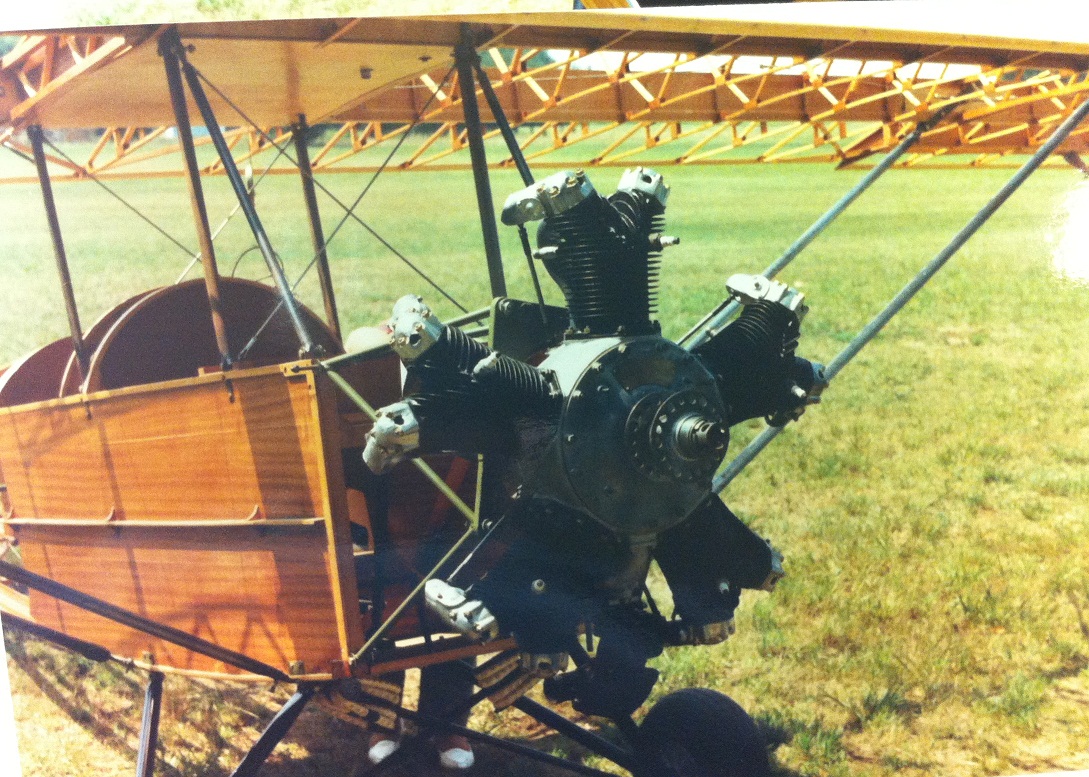
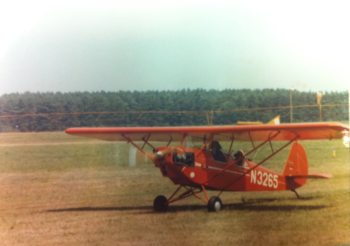